
Deployment Guide · V2.5
Channel Deployment & Station Configuration
Select the station mix and traffic model according to container types, available footprint, quay-crane demand and terminal routing.
V2.5 Automated Twist-Lock Handling Solution · 15 June 2026
3
Station configurations for different container mixes and footprints
60
Trucks per hour reference capacity for one BRT station
6
Stations operating in the twelve-quay-crane deployment model
Station Configuration
Choose by container mix and available footprint
The V2.5 solution brief defines three reference station combinations. The engineering drawing and dimensions should be validated against the terminal site before deployment.

Supported container sizes
40 ft / 45 ft
Four G-type units form the station configuration for handling 40-foot and 45-foot containers.
BRT Deployment
Bidirectional access through a shared station corridor
Each BRT-mode station supports entry and exit in both directions. The layout is designed to match quay-crane demand while reducing duplicated investment and transfer-rack movements.
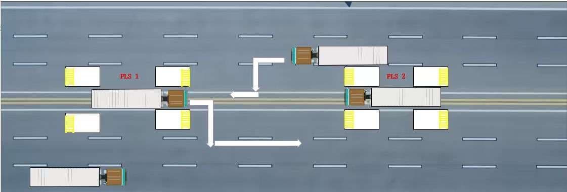
Bidirectional
Each BRT station supports traffic in both directions
60 trucks/hour
Reference processing capacity for one station
100 m
Reference corridor length shown in the deployment drawing
Large-Terminal Deployment
Twelve quay cranes across two berths
The V2.5 brief provides two reference routing models for a twelve-quay-crane terminal: a shared BRT corridor and a directional inbound/outbound layout.
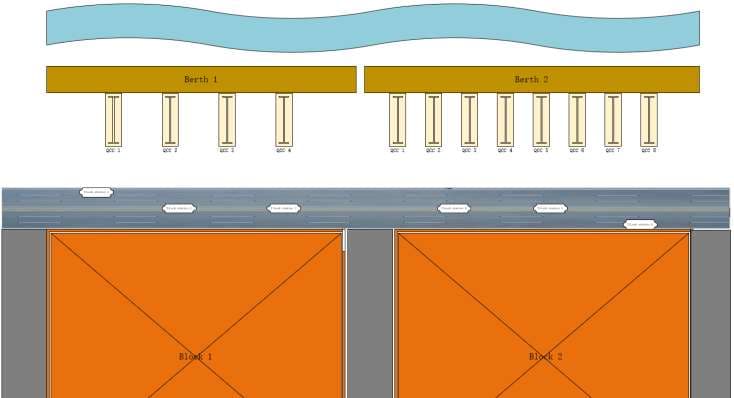
Reference model: six lock stations operating
Operating Loop
Full twist-lock flow to and from the vessel
The deployment connects quay-side handling, transfer, sorting and automatic station operations into one circulating workflow between vessel and yard.
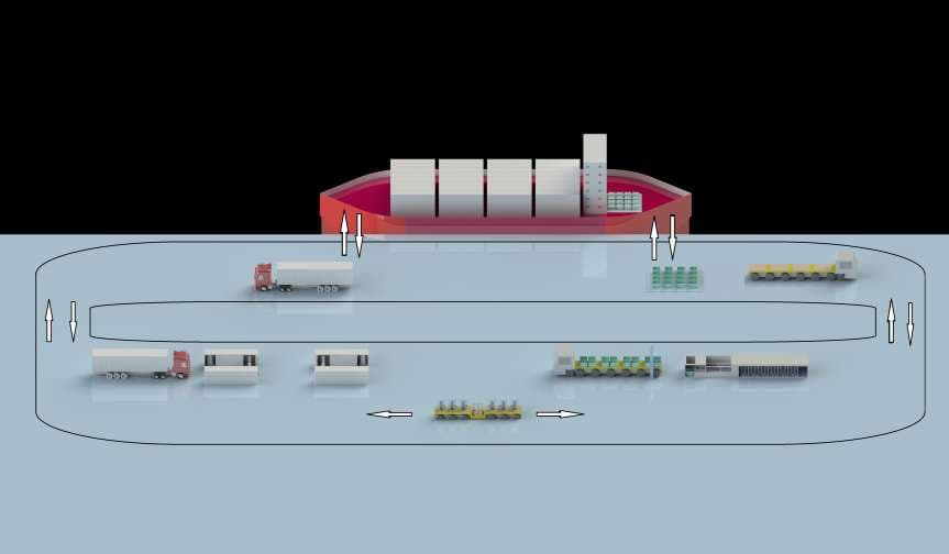
Quay-side twist-lock collection
Lock-box and transfer movement
Sorting and temporary storage
Automated station handling and return